Suzuki GSX-R Motorcycle Forums Gixxer.com banner

GSX-R 1000 k7/ k8 speedo harness pinout

15K views 25 replies 5 participants last post by  BillV  
#1 ·
#2 · (Edited)
See the wiring diagram at the back of the service manual and either the ECM terminal diagram on page 4-15 or this. AFAIK the pin numbers on the cluster connector in the wiring diagram are from 1 to 16 with 1 on the left.
If you have a cluster, I think you can see the corner pin numbers marked on the circuit board. If it was a better picture (or the case was removed), you could probably see them here:
Image
 
#5 ·
Aren't there numbers like on this?
Image

You can see 9 and 16 but 1 and 8 are probably there too. My K6 cluster has them. Here's someone else's K5/K6 and you can see 7 in one corner:

I can see what looks like a 16 (faintly) here:
Image
Your right and i think i'm blind. I don't know how i coud miss them not once but twice🤦‍♂️.
Unfortunately the order is the same as the hayabusa plug. This is the order i tried that didn't work:
Image

Image

And this is what i sourced from pictures on the internet:
Image

I'm 95% sure about the ones marked in green. The other ones are educated guesses. I don't know how they would correspond to the circuit diagram.
 
#6 · (Edited)
Here's the pinouts and wire colours for a 2010 (L0) dash. As I understand it, the K8 & K9 are the same.
Bottom right is pin 1, top right is pin 8
Image
Image

On this dash, the connector is different to that shown in Bill's pics, but the pin numbers (1, 7, 8 & 16) are clearly marked on the pcb (not the connector) & can be seen with the dash assembled.
 
#8 ·
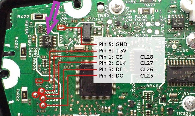
It should be possible to figure out what some of the pins correspond to with an ohmmeter. First look for an eight pin semiconductor labeled RL56. If you have one, pin 1 is on the lower left in my second pic above. Note its location relative to the indentation along the bottom. Pin 5 is the ground and is located on the upper left. You should be able to find continuity between that pin and one on the connector. That will identify connector pin #2 and the B/W lead. Similarly one side of the high beam LED should have continuity with one on the connector. That will identify pin #9 and the B/Y. One side of the neutral LED should identify pin #10 and the Bl/B. That should be enough to figure out how things are laid out.
 
#11 ·
I want to run a 1000 k8 ECM on my 750 k7 and initially thought i would change the k7 harness to fit my needs and bought a 1000 k9 harness to steal the connectors from but changed my mind in the process and changed the k9 harness to fit my 750 (this was easier).
So one thing led to another...
 
#14 ·
Many earlier diagrams showed the leads from the connector to the cluster's LEDs, as seen in Engenia's second pic above. To simplify the lead routing, they shuffled the connector lead positions around. K7/K8 seems to be a transition year with no LEDs or leads to them but with the lead positions remaining shuffled. In K9 the LEDs/leads were again missing but the connector leads were properly organized. I created a color K5/K6 wiring diagram and simply added pin numbers to the shuffled positions (several of the LEDs and the leads to them were repositioned so the leads were further shuffled). Until today I never noticed that the LEDs and the leads to them had been omitted in later years.
 
#15 ·
They actually got the circuit for the neutral LED back to front. It is activated by pulling the line low, & all of the diagrams I've seen have that line connected to the anode, which can't possibly work. ( I corrected it on my pic above) By removing the LEDs from the wiring diagram, they removed any chance of getting it wrong ;)
 
#20 ·
The K1 & K2 had two connectors between the main and front harnesses that are an endless source of problems. They're located next to the right upper fork between the triple clamps. That's the first place to check if you're having and front end electrical issues. Lazy owners tend to rig up jumpers around the connectors that end up being a horrible kludge. Identify the failed contacts and replace them. The wiring diagram in the service manual will show you what color wire is associated with what function. For example Y/Bl is the tachometer and B/G is the serial data from the ECM (tech). Note that the cluster has two power leads, one (R/Bl) is always hot while the other (O/G) is switched.
 
#22 ·
We need to know more, You mentioned the back light is OK but does everything else on the cluster work OK, ex. the tachometer, turn signal indicator, neutral indicator, etc.? If so, you might have a problem with the cluster's digital display. You could remove the cluster's circuit board from the case and look for corrosion or other damage. This shows you where to look (expand the images by clicking on them). You're not doing this to modify the board, just to check for corrosion. You could also contact him about checking the cluster, but only after you've confirmed that it's getting the necessary data.
 
#26 ·
So I gather that the backlight and various LED indicators work (except the red fault indicator). As best I know, the fault indicator sits apart from the digital display, both being controlled by the big IC in the circuit board (it may also control the shift light). The other indicators have fairly simple circuits, they're essentially driven directly by the associated leads to the board. I also think that the tach is controlled by the second biggest IC. So it sounds like the board has at least power and a ground but the major chips are dead. Make sure that both power leads are at battery voltage. Then start checking the circuit board for corrosion and/or damage. You might need a new cluster.